
R, C and L Phasors
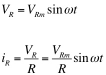
In a circuit with only the ac generator providing a voltage, V(t) = VRm sinωt, and a resistance, R, the voltage and current across the resistor are given by,
Note that the current and voltage phasors are in phase, as shown in the diagram at right.
Note that in all phasor diagrams the magnitude of the phasors is the maximum value of the current or voltage, referred to as VRm and IRm .
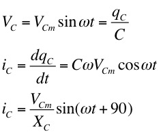
With the generator and a capacitance, we have,
whereis called the capacitive reactance.
Note that in this case the current phasor leads the voltage phasor by 900.
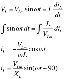
With the generator and inductance alone, we have,
whereis called the inductive reactance.
Note that in this case the current phasor lags the voltage phasor by 900.
Series LCR Circuits
 Combining these
three elements - resistance, capacitance and inductance
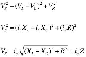
- in a series (LCR) circuit we may write
Combining these
three elements - resistance, capacitance and inductance
- in a series (LCR) circuit we may writeNow, treating these potentials as vectors (phasors), using the combined phasor diagram below we have
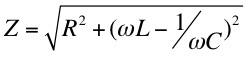
where im is the maximum current provided by the generator and Z is called the impedance, which plays a similar role to resistance in d.c. circuits. In terms of the resistance, capacitance and inductance the impedance can be written,
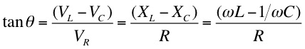
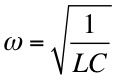 , XC = XL so that
tanθ = 0 (θ = 0) and Z = R. That is,
the circuit is purely resistive with the current
and voltage in phase.
, XC = XL so that
tanθ = 0 (θ = 0) and Z = R. That is,
the circuit is purely resistive with the current
and voltage in phase.Power Dissipation
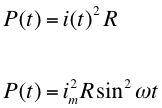
As we have seen in the simple LC circuit the inductance (L) and capacitance (C) do not dissipate energy. The energy simply oscillates from magnetic to electric without limit. So in an LCR circuit energy can only be dissipated (lost) in the resistance (R). The power dissipated is given by,
whereis the "root-mean-square" of the maximum current.
AC current and voltage measuring devices are usually calibrated to read rms values. In fact the 110 volts in a wall outlet is actually the rms value. The maximum voltage is given by 110 x √2 = 170 V.
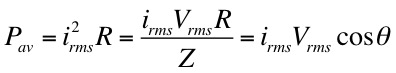
where from the LCR phasor diagram we see that cosθ = R/Z.
Maximum power dissipation occurs when cosθ = 1 or R = Z - the circuit is purely resistive.
Famous Physicists at a party : Volt thought the social had a lot of potential.

Dr. C. L. Davis
Physics Department
University of Louisville
email: c.l.davis@louisville.edu